Galvanic isolation refers to the principle in which two circuits are electrically completely isolated from each other, although signals or energy can still be transmitted between them. This is usually done by components such as transformers, optocouplers or special coupling elements that do not use a direct electrical connection, but rather a magnetic or optical coupling, for example.
Galvanic isolation on the USB port makes sense for several reasons and has both safety and practical advantages.
Protection against voltage differences and overvoltage.
USB connections normally provide a direct electrical connection between the PC (host) and connected devices. If overvoltages occur due to lightning strikes, switching operations or electrostatic discharge, dangerous equalizing currents can flow, which can cause irreparable damage to the hardware. Galvanic isolation prevents such voltage peaks or potential differences from being passed from one device to another.
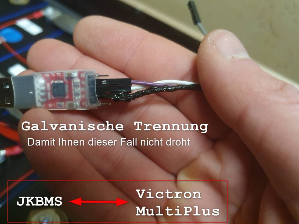
The picture shows scorched cable parts. Here, excessive currents from a correctly connected JKBMS to a 16s battery (48V) caused the damage. The FT232 adapter was destroyed. Fortunately, not the USB port or the board of the Victron Multiplus 2.
Use our galvanically isolated adapter with FT232RL chip. Order here.
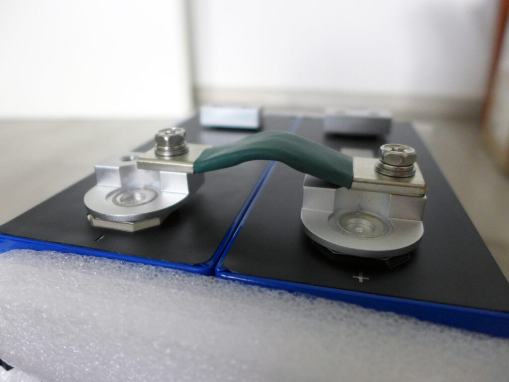
For LiFePO4 batteries, when connecting cells in parallel (16S2P, 8S2P, 4S2P), the threads of the terminals are usually not long enough. These measure 12mm for prismatic cells, sometimes 14mm. Especially for batteries that use 12V or 24V, our 6mm thick connectors are necessary. Two connectors on top of each other result in 12mm, leaving no room for a nut for fastening.
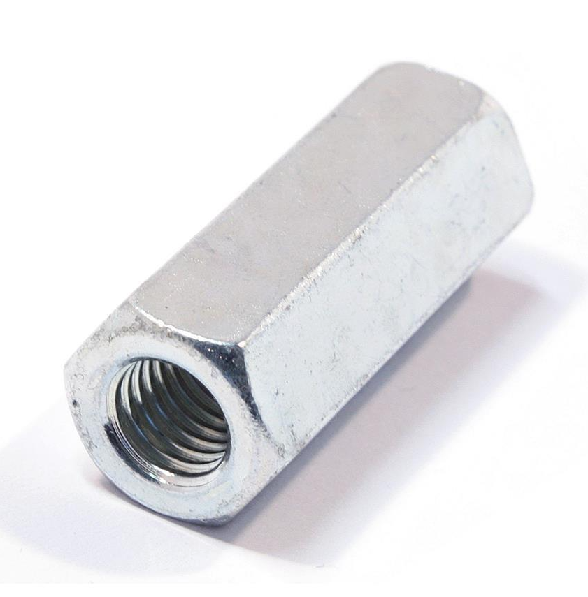
M6 x 30 mm connecting sleeve. Steel, galvanically zinc-plated. Hexagonal, internal thread.
How can parallel connections be implemented in an LFP battery?
The terminals must be extended. A long nut / connecting sleeve is ideal for this. Dimensions: M6 x 30mm. This is screwed onto the terminal and offers an internal thread at the top for any extension by a second threaded rod. This makes it easy to attach two connectors on top of each other and close them with a flat nut.
In our shop, you can choose between two connector variants, 220 amps and 300 amps load capacity. This article explains which LFP connectors are suitable for which charging and discharging currents.
I Know the Output of My Solar System and the Voltage (Volts) of My Energy Storage.
Many planners of a DIY home storage system initially only know the peak output of their solar system in kWp. The following table shows the maximum load capacity of the LiFePO4 connectors in relation to the peak output of the solar system. Example: My 48-volt energy storage system with LiFePO4 connectors up to 220 amps can roughly be charged with a solar system up to 10.5 kWp.
Calculation examples for the 220A version of the connectors:
I Know My Multiplus and the Voltage (Volts) of My Energy Storage.
The energy storage is charged with the Victron Multiplus 2 in charger mode and discharged in inverter mode. The maximum charging current can be found in the Multiplus data sheet under Charger -> Maximum battery charging current. The maximum discharge current can be found in the table below. The formula is \( I = P / U \) or \( Ampere = Watt / Volt \).
If you know which Victron Multiplus 2 you want to use and whether you want to build a 48 volt, 24 volt or 12 volt energy storage system, the following tables will help you:
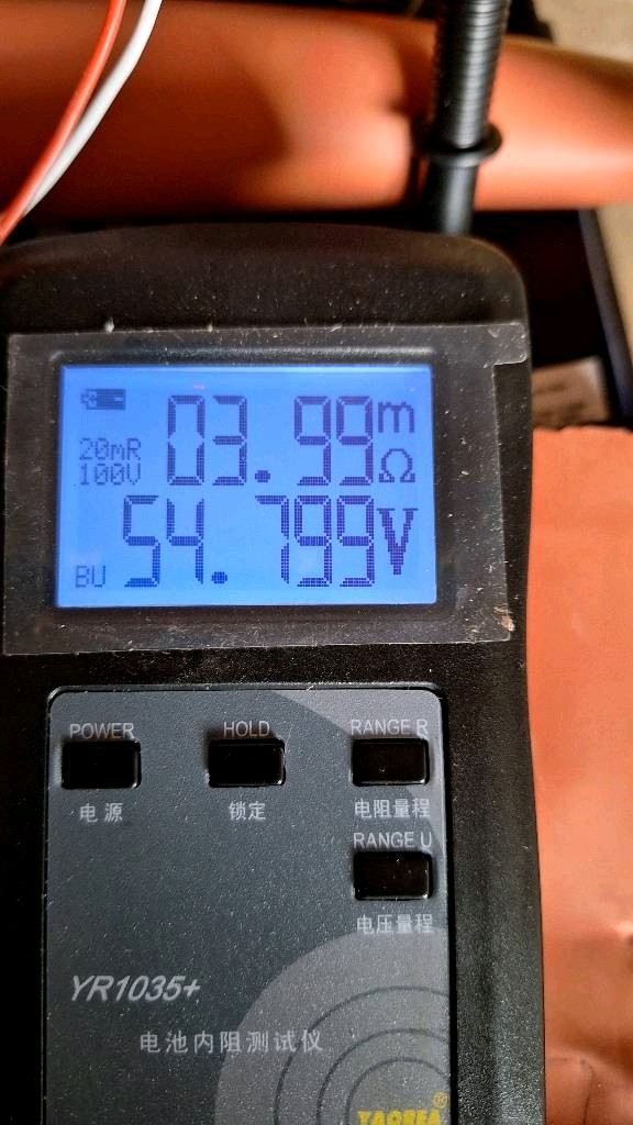
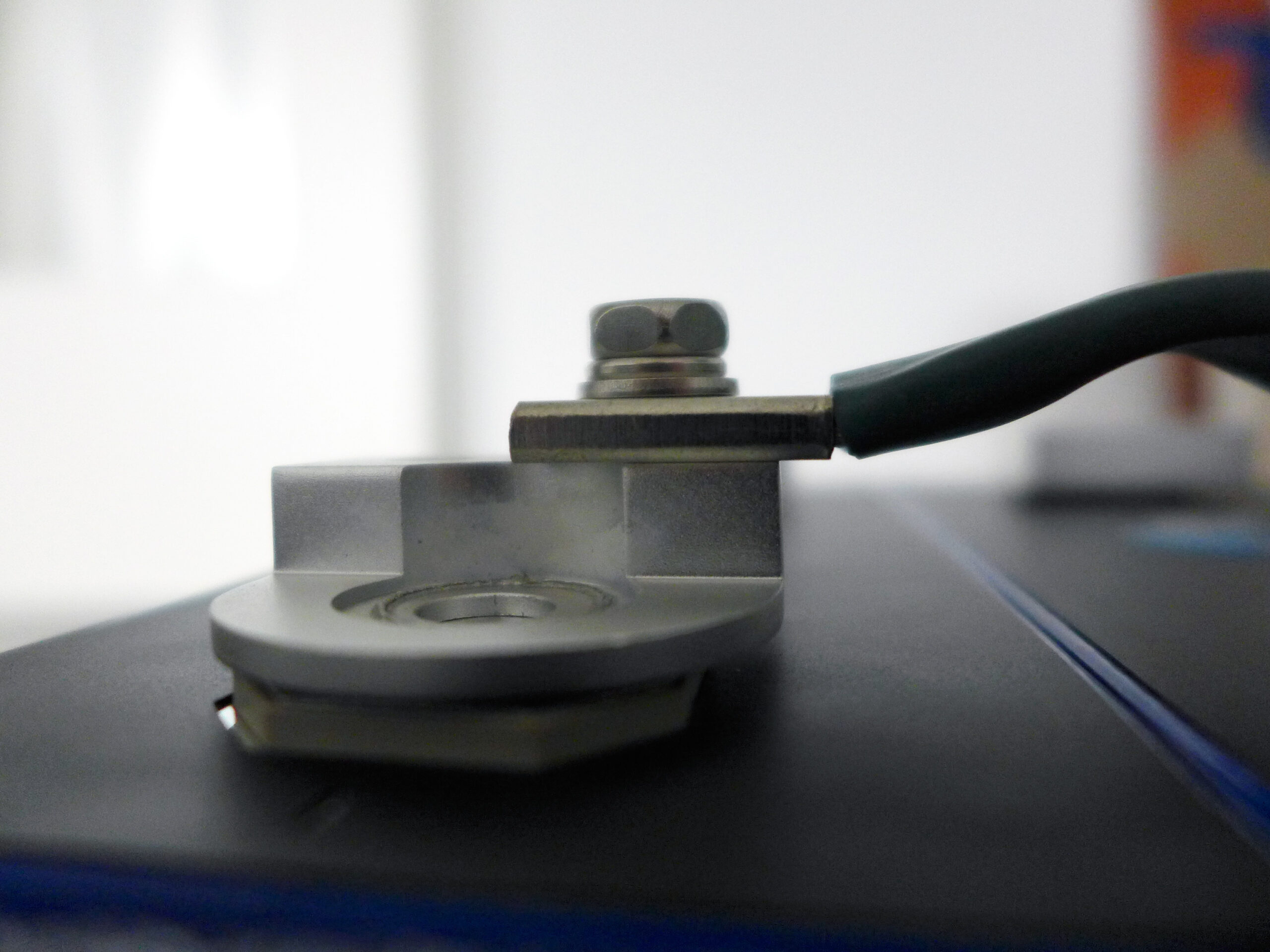
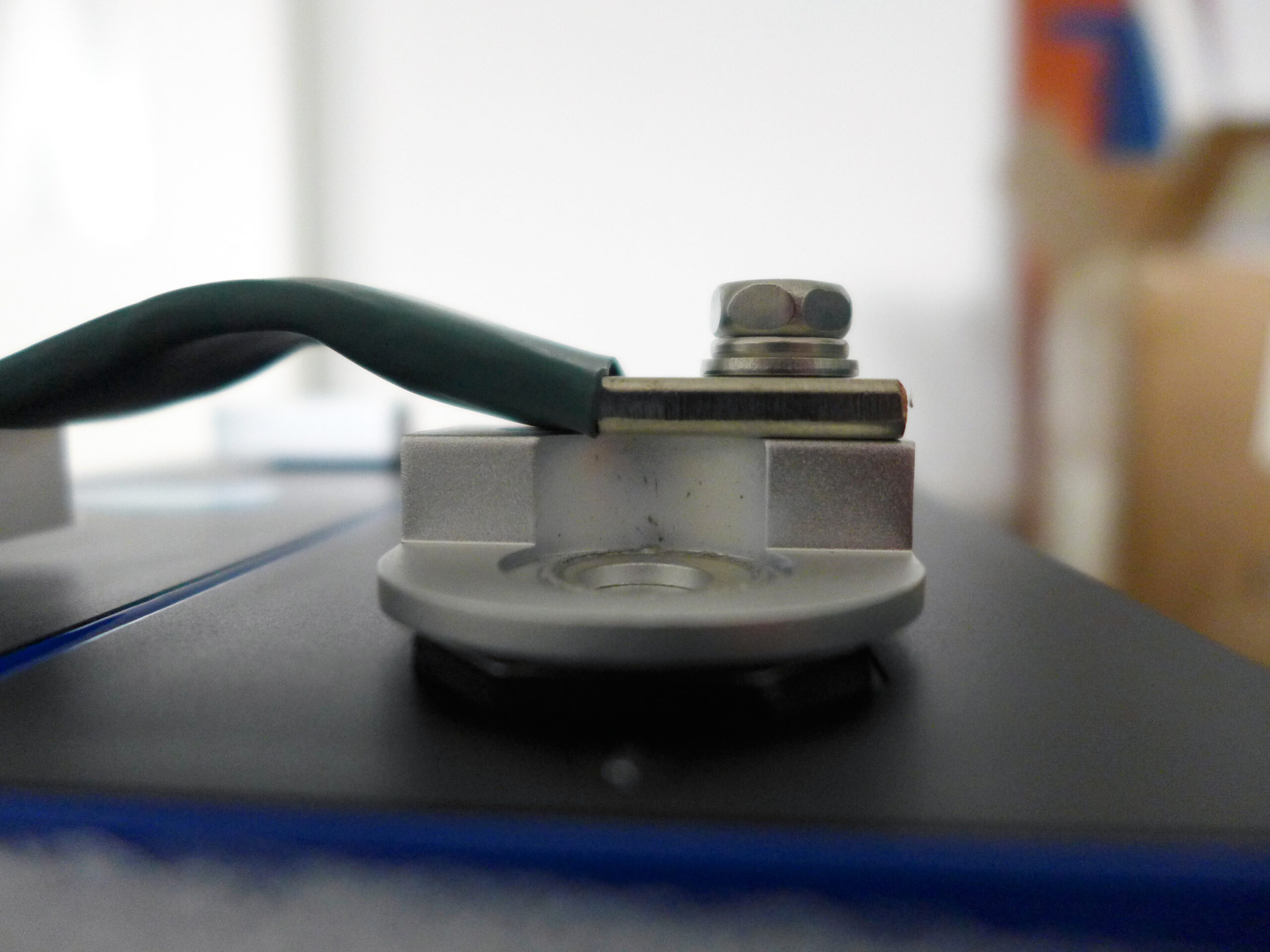
Our customer Armin has professionally measured our 50mm² LFP connector and is more than satisfied.
Here is his conclusion:
Contact resistance of the connectors from pole to pole from 0.14 to 0.12mOhm per connector!
I have now provided the connectors with additional M3 holes for the voltage tap or JKBMS / balancer.
The contact surfaces are coated with graphite paste and assembled with 5Nm. Previously cleaned both contact surfaces with abrasive fleece and degreased with ethanol.
I measured an amazing value of less than 4mOhm on the entire pack. That is (what I think) more than OK.
If I subtract the internal resistance of 0.16mOhm measured on the cell during the first charging cycle (16S = 2.56mOhm), about 1.44mOhm remain on 15 connectors.
Only 0.095mOhm are lost per connector, which is a good improvement.
I am more than satisfied and honestly didn’t expect that.
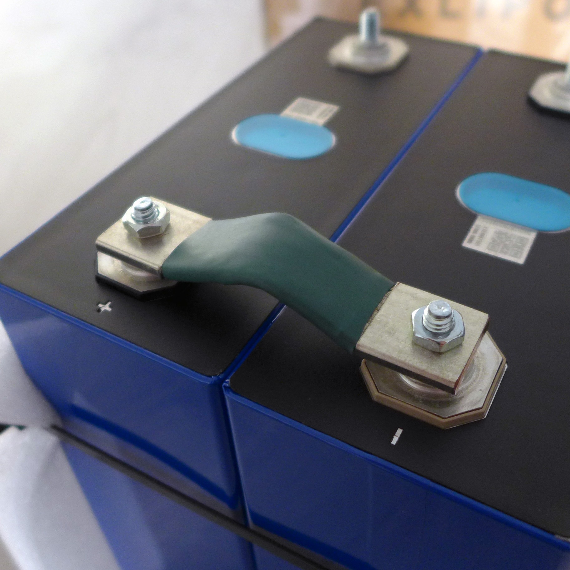
The terminals of the new EVE LF280K V3 Prismatic cells with 280Ah have terminals with double bore and larger contact surface compared to cells from CATL or similar.
There are online LiFePO4 connectors with double bore, which were developed especially for these cells. They enable an optimal connection between the cells and reduce the resistance.
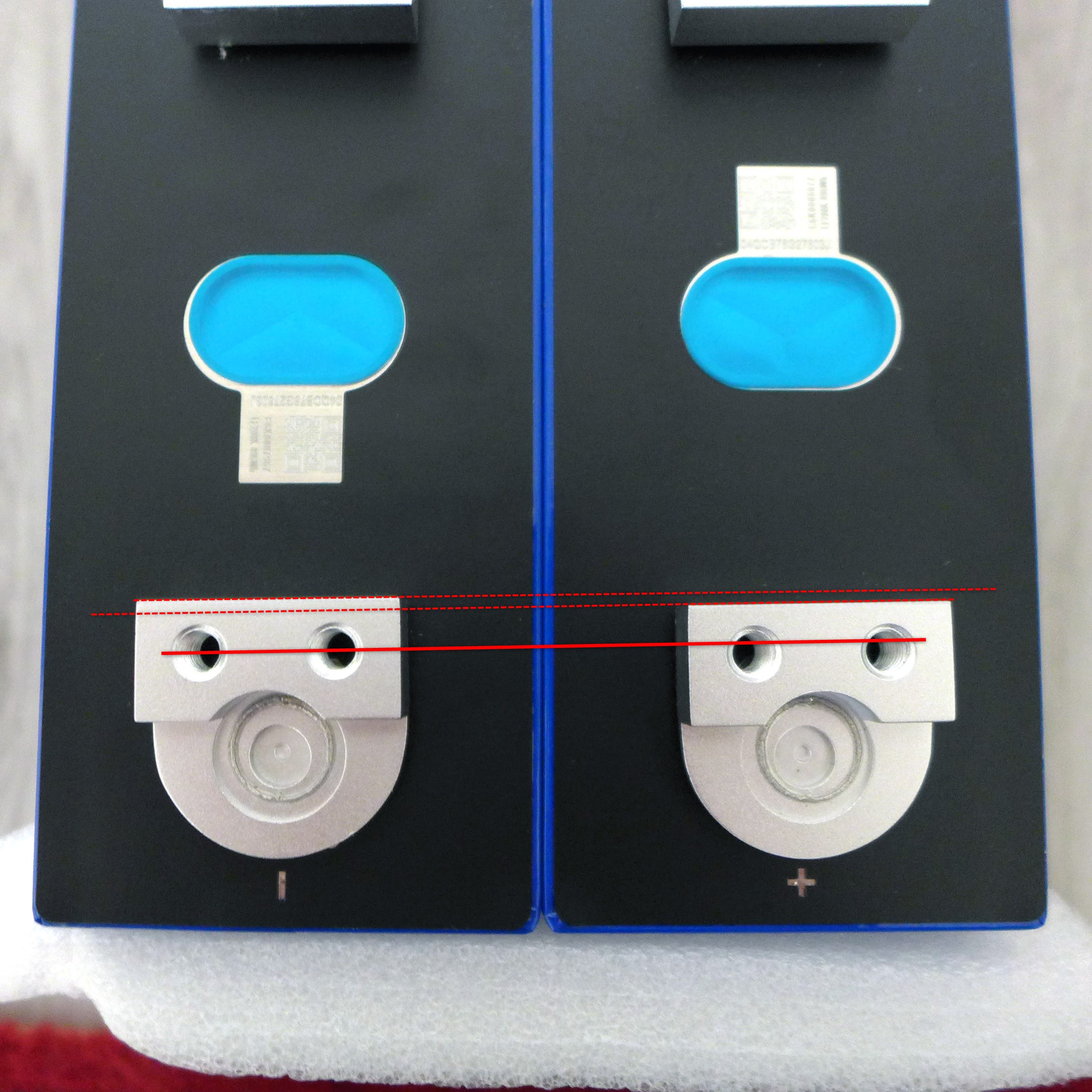
However, there is a problem: The terminals of the cells are often so unevenly mounted that the use of double-bore connectors is not possible. The cells in the photo are original EVE LF280K V3 Grade A cells, and marking lines have been added to illustrate the offset.
Therefore, we recommend our single-bore LiFePO4 connectors with a thickness of 35 or 50 mm² for EVE LF280K V3 cells. These make it possible to easily compensate for the offset of the terminals and operate the battery safely and without mechanical stress.
LiFePO4 cells can expand during operation, causing them to bulge. Incorrect or insufficient bracing of the LFP cells promotes this expansion. The expansion increases the distance between the cell terminals.
When using rigid connectors with fixed screw connections, the connectors may pull on the cell terminals, which can lead to damage or destruction of the LFP cell. The distance between the terminals of the cells is 72 mm. Our connectors have a hole spacing of 75 mm, which provides 3 mm of play to compensate for cell expansion. This keeps the terminals free of mechanical tension throughout their service life.